Overview
The EQSS Crush Guard® is a secondary guarding solution designed in Australia for use with elevated work platforms (EWP).
Request Quote
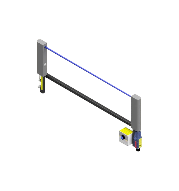
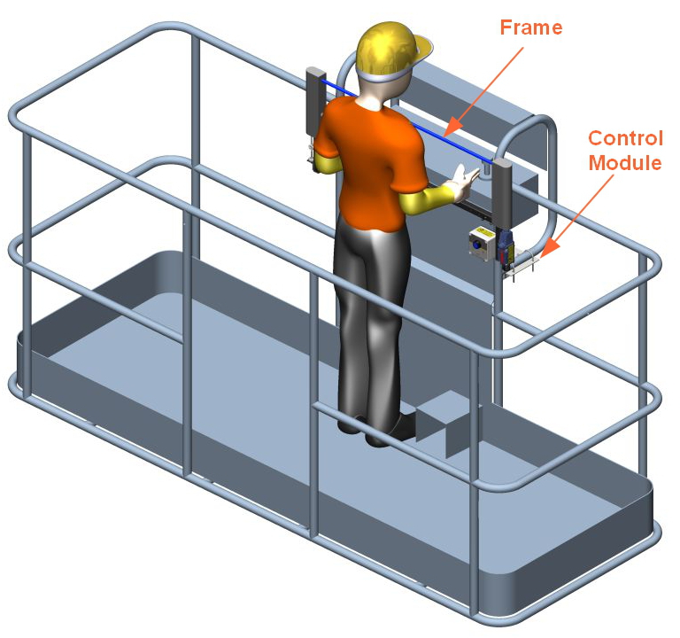
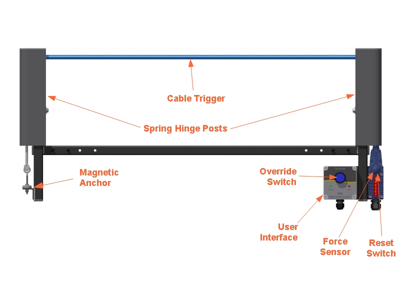
The Crush Guard® uses a pressure sensitive wire rope positioned over the EWP controls. When a crushing incident occurs forcing the operator on to the wire rope, the alarm is triggered preventing further movement. A force from any direction applied to the wire rope will trigger the alarm.
The wire rope is attached using a magnetic anchoring system. If force continues to be applied to the wire rope after the alarm has been triggered, the magnetic anchor will break away making the wire rope go slack, preventing the operator from being crushed by the wire rope. Once the crush hazard has been avoided it is a simple matter of reconnecting the magnet to the anchor point to return the machine to normal operation.
One of the major advantages to the Crush Guard® over existing EWP secondary guarding solutions is the use of a break-away pressure sensitive wire rope over the traditional pressure bar. Systems that operate using a pressure bar require the operator to lean on the bar at a certain angle to trigger the system, if the pressure bar is positioned at the correct angle or the operator is not of the correct height the pressure bar will not trigger and the operator will be killed or seriously injured. If the operator does trigger the pressure bar, the inertia from the machine movement before it comes to a stop will crush the operator against the pressure bar itself, again killing or seriously injuring the operator.
Some pressure bars are attached using breakaway tabs, which cause the pressure bar to break off if excessive force is applied, when this occurs the machine will be no longer operational until replacement breakaway tabs are ordered and installed. As the Crush Guard uses a magnetic breakaway system, the operator just needs to reattach the magnet and the machine is ready to go back to work.
Due to its position it is easy for the operator to falsely trigger the pressure bar by leaning towards the controls in order to steady themselves while the EWP is moving. The wire rope is mounted in a position requiring the operator to place their hands underneath the wire rope to reach the controls. This allows the operator to leaning on the machine or frame of the Crush Guard® without falsely triggering the system.
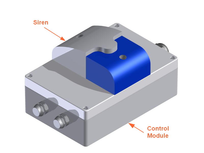
The Crush Guard® uses two independently controlled processors to detect when the alarm has been triggered and to engage the EWP hydraulic cutout to prevent further movement. The Crush Guard® has been designed based on ISO13849 and has a category 3 architecture and meets performance level D.


